 |
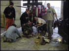 |
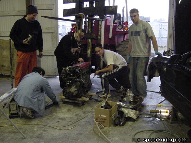
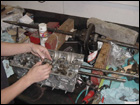
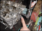
The first thing to do is pull the motor. Done in record time - 45mins |
 |
 |
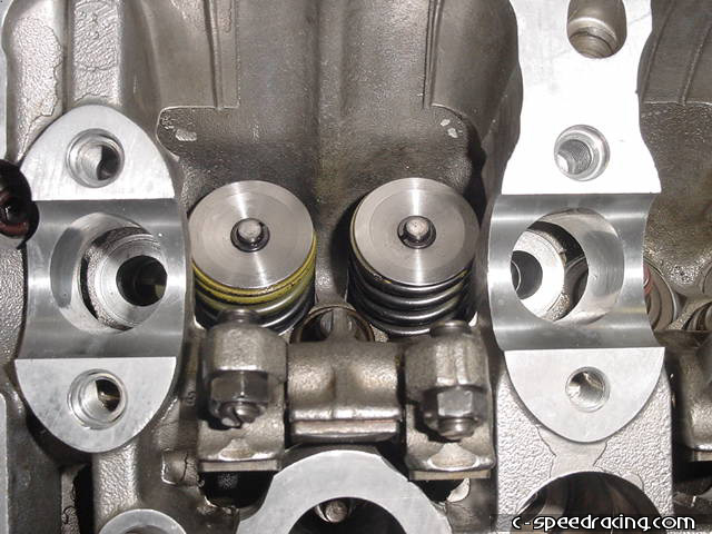
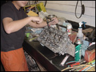
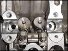
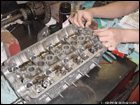
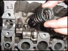
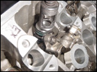
Once the motor was torn down, the first part of building a strong NA monster is a crazy valvetrain. Here we install ITR outer spings and Portflow inner springs and titanium retainers. This should be good for 10,000rpms redline. |
 |
 |
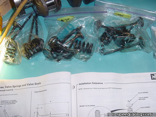
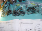
When you do the tear down, cleanliness and organization is key. Make sure you label everything and Ziplock bags come in real handy and are perfect for the job. |
 |
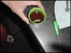 |
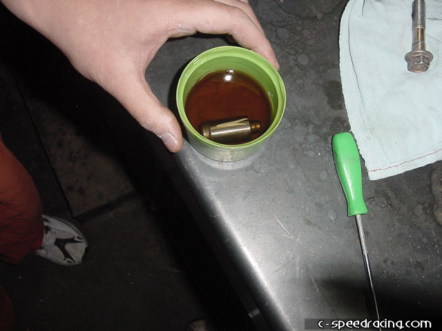
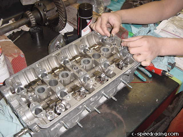
Make sure you replace all the components in the same location that you removed them from as they each have different wear characteristics. Also be sure to soak the lost motion assembly in oil before you install it back into the head or else you might end up with some loud ticking afterwards. |
 |
 |
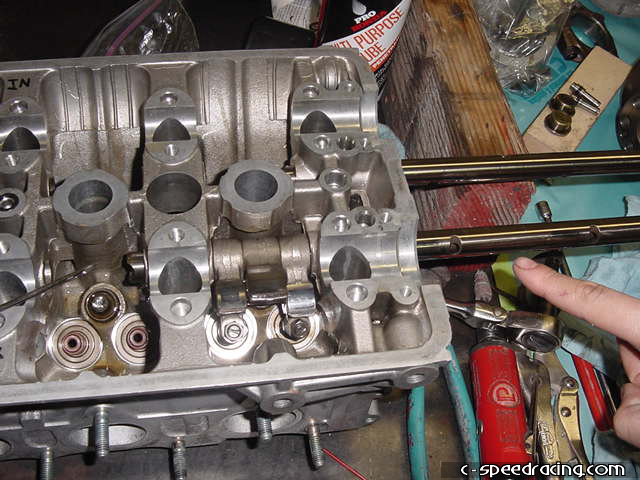
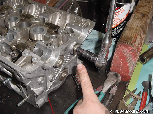
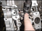
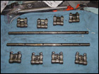
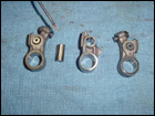
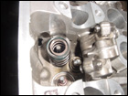
Be careful when removing and installing the valve lifter shafts. They are specific to the intake and exhaust side and are keyed for up and down direction. |
 |
 |
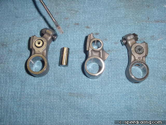
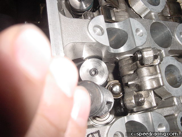
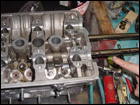
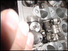
Here you can see the individual components of the valve lifters. You can see the small piston that is oil activated to engage VTEC. Also make sure you install the oil control orifices correctly. |
 |
 |
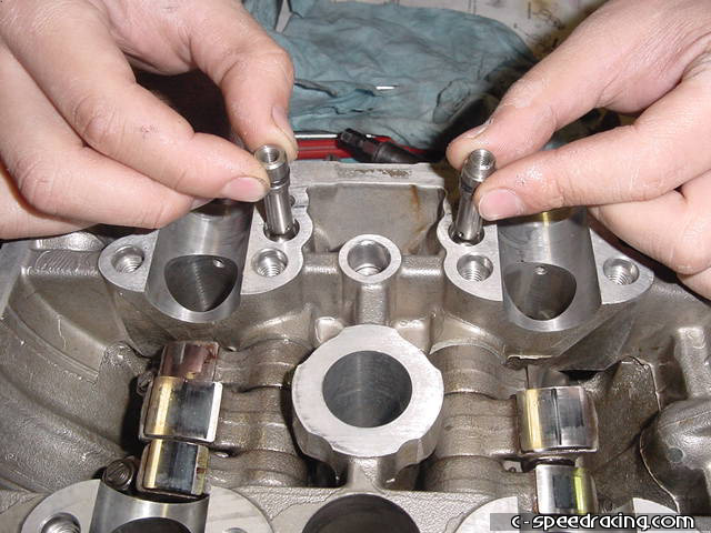
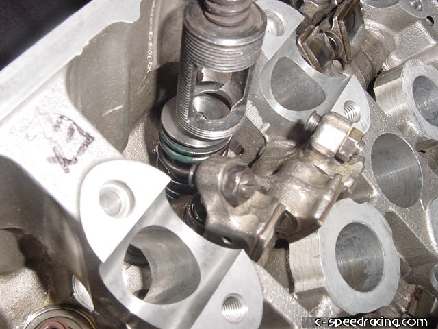
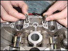
Make sure you have the lifters correctly installed and the oil control orifices in place. Then torque the end caps to spec. |
 |
 |
When you install the new valve springs, make sure you take notice to the direction they are facing. There is an up and down to them. The ITR springs are colored blue and yellow. Be sure the colored side faces up. Blue on the exhaust side and yellow on the intake side. |
 |
 |
To install the valve keepers, use a valve spring compressor. Then carefully place the keepers onto the valve stem and gently release the spring compressor. Patience and practice is vital at this stage. |